(Q series) external tooth type
Category:
Slewing ring bearing
Key words:
Slewing ring bearing
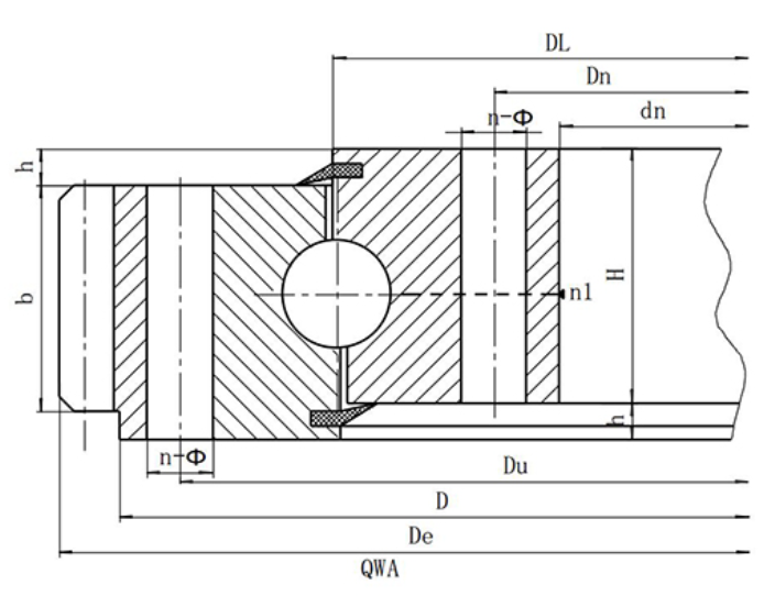
(Q series) single row four-point contact ball slewing ring-external tooth type
Structural characteristics, performance and scope of application
Single-row four-point contact ball slewing bearing is composed of two seat rings, compact structure, light weight, steel ball and arc raceway four-point contact, can bear axial force, radial force and tilting moment, rotary conveyor, welding manipulator, small and medium-sized cranes and excavators and other construction machinery can be selected.
| Serial Number | Model | Overall dimension | Mounting hole size | Structure size | Gear parameters | ||||||||||||
| external tooth type | H | Du | Dn | n | Through hole A | Screw hole B/C/D | n1 oil cup Quantity |
h | B | m | External tooth type x =-0.5 | ||||||
| De | Number of teeth z | Weight | |||||||||||||||
| D | d | φ | d1 | T | |||||||||||||
| mm | mm | mm | mm | kg | |||||||||||||
| 1 | QW.315.20 | 406 | 222 | 60 | 370 | 260 | 10 | 17 | M16 | 24 | 2 | 10 | 40 | 3 | 423 | 140 | 35 |
| QW.315.20A | 4 | 428 | 106 | 36 | |||||||||||||
| 2 | QW.355.20 | 446 | 262 | 60 | 410 | 300 | 10 | 17 | M16 | 24 | 2 | 10 | 40 | 3 | 462 | 153 | 40 |
| QW.355.20A | 4 | 468 | 116 | 41 | |||||||||||||
| 3 | QW.400.20 | 490 | 307 | 60 | 455 | 345 | 12 | 17 | M16 | 24 | 2 | 10 | 40 | 4 | 512 | 127 | 45 |
| QW.400.20A | 5 | 520 | 103 | 47 | |||||||||||||
| 4 | QW.450.20 | 540 | 357 | 60 | 505 | 395 | 12 | 17 | M16 | 24 | 2 | 10 | 40 | 4 | 564 | 140 | 51 |
| QW.450.20A | 5 | 570 | 113 | 53 | |||||||||||||
| 5 | QW.500.20 | 590 | 407 | 60 | 555 | 445 | 14 | 17 | M16 | 24 | 2 | 10 | 40 | 5 | 615 | 122 | 56 |
| QW.500.20A | 6 | 624 | 103 | 58 | |||||||||||||
| 6 | QW.560.20 | 654 | 464 | 70 | 618 | 502 | 14 | 17 | M16 | 30 | 2 | 10 | 50 | 4 | 680 | 169 | 78 |
| QW.560.20A | 5 | 685 | 136 | 79 | |||||||||||||
| 7 | QW.630.20 | 724 | 534 | 70 | 688 | 572 | 16 | 17 | M16 | 30 | 2 | 10 | 50 | 4 | 748 | 186 | 86 |
| QW.630.20A | 5 | 755 | 150 | 88 | |||||||||||||
| 8 | QW.710.20 | 804 | 614 | 70 | 768 | 652 | 18 | 17 | M16 | 30 | 2 | 10 | 50 | 5 | 835 | 166 | 99 |
| QW.710.20A | 6 | 840 | 139 | 101 | |||||||||||||
| 9 | QW.800.20 | 894 | 704 | 70 | 858 | 742 | 20 | 17 | M16 | 30 | 2 | 10 | 50 | 6 | 930 | 154 | 114 |
| QW.800.20A | 8 | 936 | 116 | 114 | |||||||||||||
| 10 | QW.800.25 | 904 | 692 | 78 | 864 | 736 | 18 | 22 | M20 | 36 | 2 | 10 | 58 | 6 | 942 | 156 | 143 |
| QW.800.25A | 8 | 952 | 118 | 147 | |||||||||||||
| 11 | QW.900.25 | 1004 | 792 | 78 | 964 | 836 | 20 | 22 | M20 | 36 | 2 | 10 | 58 | 8 | 1048 | 130 | 162 |
| QW.900.25A | 10 | 1060 | 105 | 168 | |||||||||||||
| 12 | QW.1000.25 | 1104 | 892 | 78 | 1064 | 936 | 24 | 22 | M20 | 36 | 2 | 10 | 58 | 8 | 1152 | 143 | 182 |
| QW.1000.25A | 10 | 1160 | 115 | 185 | |||||||||||||
| 13 | QW.1000.32 | 1120 | 876 | 90 | 1074 | 926 | 24 | 24 | M22 | 40 | 2 | 10 | 70 | 8 | 1160 | 144 | 227 |
| QW.1000.32A | 10 | 1170 | 116 | 232 | |||||||||||||
| 14 | QW.1120.32 | 1240 | 996 | 90 | 1194 | 1046 | 28 | 24 | M22 | 40 | 4 | 10 | 70 | 10 | 1300 | 129 | 272 |
| QW.1120.32A | 12 | 1308 | 108 | 275 | |||||||||||||
| 15 | QW.1250.32 | 1370 | 1126 | 90 | 1324 | 1176 | 32 | 24 | M22 | 40 | 4 | 10 | 70 | 10 | 1430 | 142 | 302 |
| QW.1250.32A | 12 | 1440 | 119 | 309 | |||||||||||||
| 16 | QW.1400.32 | 1520 | 1276 | 90 | 1474 | 1326 | 36 | 24 | M22 | 40 | 4 | 10 | 70 | 12 | 1584 | 131 | 337 |
| QW.1400.32A | 14 | 1596 | 113 | 347 | |||||||||||||
| 17 | QW.1250.40 | 1390 | 1108 | 102 | 1336 | 1164 | 32 | 26 | M24 | 45 | 4 | 12 | 80 | 10 | 1450 | 144 | 396 |
| QW.1250.40A | 12 | 1452 | 120 | 392 | |||||||||||||
| 18 | QW.1400.40 | 1540 | 1258 | 102 | 1486 | 1314 | 36 | 26 | M24 | 45 | 4 | 12 | 80 | 12 | 1608 | 133 | 448 |
| QW.1400.40A | 14 | 1610 | 114 | 443 | |||||||||||||
| 19 | QW.1600.40 | 1740 | 1458 | 102 | 1686 | 1514 | 40 | 26 | M24 | 45 | 4 | 12 | 80 | 12 | 1812 | 150 | 528 |
| QW.1600.40A | 14 | 1820 | 129 | 534 | |||||||||||||
| 20 | QW.1800.40 | 1940 | 1658 | 102 | 1886 | 1714 | 44 | 26 | M24 | 45 | 4 | 12 | 80 | 14 | 2016 | 143 | 583 |
| QW.1800.40A | 16 | 2032 | 126 | 607 | |||||||||||||
| 21 | QW.1600.50 | 1762 | 1434 | 124 | 1704 | 1496 | 40 | 30 | M27 | 50 | 4 | 12 | 100 | 12 | 1824 | 151 | 714 |
| QW.1600.50A | 14 | 1834 | 130 | 727 | |||||||||||||
| 22 | QW.1800.50 | 1964 | 1634 | 124 | 1904 | 1696 | 44 | 30 | M27 | 50 | 4 | 12 | 100 | 14 | 2044 | 145 | 845 |
| QW.1800.50A | 16 | 2048 | 127 | 843 | |||||||||||||
| 23 | QW.2000.50 | 2162 | 1834 | 124 | 2104 | 1896 | 48 | 30 | M27 | 50 | 6 | 12 | 100 | 16 | 2240 | 139 | 912 |
| QW.2000.50A | 18 | 2250 | 124 | 927 | |||||||||||||
| 24 | QW.2240.50 | 2402 | 2074 | 124 | 2344 | 2136 | 54 | 30 | M27 | 50 | 6 | 12 | 100 | 16 | 2480 | 154 | 1020 |
| QW.2240.50A | 18 | 2502 | 138 | 1078 | |||||||||||||
| 25 | QW.2500.50 | 2662 | 2334 | 124 | 2604 | 2396 | 60 | 30 | M27 | 50 | 6 | 12 | 100 | 18 | 2754 | 152 | 1171 |
| QW.2500.50A | 20 | 2760 | 137 | 1175 | |||||||||||||
| 26 | QW.2500.60 | 2696 | 2304 | 150 | 2626 | 2374 | 60 | 33 | M30 | 56 | 6 | 14 | 122 | 18 | 2790 | 154 | 1677 |
| QW.2500.60A | 20 | 2800 | 139 | 1701 | |||||||||||||
Note:
1. n1 is the number of lubricating oil holes, evenly distributed: oil cup M10 × 1 JB/T7940.1-JB/T7940.2
2. Installation hole n-Φ can be replaced by screw hole; Tooth width B can be changed to H-h.
3. The circumferential force of the gear in the table is the maximum circumferential force, and the rated circumferential force is 1/2.
Related Products
Online message

Product classification
Contact Us