(Q Series) Toothless
Category:
Slewing ring bearing
Key words:
Slewing ring bearing
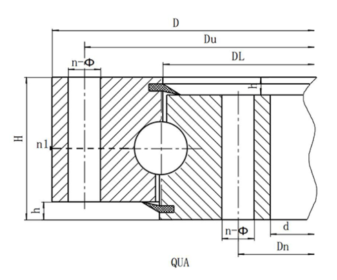
(Q series) single row four-point contact ball slewing ring-toothless type
Structural characteristics, performance and scope of application
Single-row four-point contact ball slewing bearing is composed of two seat rings, compact structure, light weight, steel ball and arc raceway four-point contact, can bear axial force, radial force and tilting moment, rotary conveyor, welding manipulator, small and medium-sized cranes and excavators and other construction machinery can be selected.
| Serial Number | Model | Overall dimension | Mounting hole size | Structure size | Weight | ||||||||
| toothless type | H | Du | Dn | n | Through hole A | Screw hole B/C/D | n1 oil cup Quantity |
h | |||||
| D | d | φ | d1 | T | |||||||||
| mm | mm | mm | Kg | ||||||||||
| 1 | Fan. 315.20 | 408 | 222 | 60 | 370 | 260 | 10 | 17 | M16 | 24 | 2 | 10 | 34 |
| 2 | Fan. 355.20 | 448 | 262 | 60 | 410 | 300 | 10 | 17 | M16 | 24 | 2 | 10 | 39 |
| 3 | Fan. 400.20 | 493 | 307 | 60 | 455 | 345 | 12 | 17 | M16 | 24 | 2 | 10 | 44 |
| 4 | Fan. 450.20 | 543 | 357 | 60 | 505 | 395 | 12 | 17 | M16 | 24 | 2 | 10 | 50 |
| 5 | Fan. 500.20 | 593 | 407 | 60 | 555 | 445 | 14 | 17 | M16 | 24 | 2 | 10 | 55 |
| 6 | Qu.560.20 | 656 | 464 | 70 | 618 | 502 | 14 | 17 | M16 | 30 | 2 | 10 | 76 |
| 7 | Qu.630.20 | 726 | 534 | 70 | 688 | 572 | 16 | 17 | M16 | 30 | 2 | 10 | 84 |
| 8 | Fan. 710.20 | 806 | 614 | 70 | 768 | 652 | 18 | 17 | M16 | 30 | 2 | 10 | 97 |
| 9 | Qu.800.20 | 896 | 704 | 70 | 858 | 742 | 20 | 17 | M16 | 30 | 2 | 10 | 110 |
| 10 | Qu.800.25 | 908 | 692 | 78 | 864 | 736 | 18 | 22 | M20 | 36 | 2 | 10 | 142 |
| 11 | Fan. 900.25 | 1008 | 792 | 78 | 964 | 836 | 20 | 22 | M20 | 36 | 2 | 10 | 163 |
| 12 | Fan. 1000.25 | 1108 | 892 | 78 | 1064 | 936 | 24 | 22 | M20 | 36 | 2 | 10 | 178 |
| 13 | Fan. 1000.32 | 1124 | 876 | 90 | 1074 | 926 | 24 | 24 | M22 | 40 | 2 | 10 | 230 |
| 14 | Fan. 1120.32 | 1244 | 996 | 90 | 1194 | 1046 | 28 | 24 | M22 | 40 | 4 | 10 | 263 |
| 15 | Fan. 1250.32 | 1374 | 1126 | 90 | 1324 | 1176 | 32 | 24 | M22 | 40 | 4 | 10 | 294 |
| 16 | Fan. 1400.32 | 1524 | 1276 | 90 | 1474 | 1326 | 36 | 24 | M22 | 40 | 4 | 10 | 333 |
| 17 | Fan. 1250.40 | 1394 | 1108 | 102 | 1336 | 1164 | 32 | 26 | M24 | 45 | 4 | 12 | 388 |
| 18 | Fan. 1400.40 | 1544 | 1258 | 102 | 1486 | 1314 | 36 | 26 | M24 | 45 | 4 | 12 | 444 |
| 19 | Fan. 1600.40 | 1744 | 1458 | 102 | 1686 | 1514 | 40 | 26 | M24 | 45 | 4 | 12 | 509 |
| 20 | Fan. 1800.40 | 1944 | 1658 | 102 | 1886 | 1714 | 44 | 26 | M24 | 45 | 4 | 12 | 576 |
| 21 | Fan. 1600.50 | 1766 | 1434 | 124 | 1704 | 1496 | 40 | 30 | M27 | 50 | 4 | 12 | 714 |
| 22 | Fan. 1800.50 | 1966 | 1634 | 124 | 1904 | 1696 | 44 | 30 | M27 | 50 | 4 | 12 | 794 |
| 23 | Qu.200850 | 2166 | 1834 | 124 | 2104 | 1896 | 48 | 30 | M27 | 50 | 6 | 12 | 891 |
| 24 | Qu.22430 | 2406 | 2074 | 124 | 2344 | 2136 | 54 | 30 | M27 | 50 | 6 | 12 | 1044 |
| 25 | Fan. 2500.50 | 2666 | 2334 | 124 | 2604 | 2396 | 60 | 30 | M27 | 50 | 6 | 12 | 1132 |
| 26 | Fan. 2500.60 | 2696 | 2304 | 150 | 2626 | 2374 | 60 | 33 | M30 | 56 | 6 | 14 | 1621 |
Note:
1. n1 is the number of lubricating oil holes, evenly distributed: oil cup M10 × 1 JB/T7940.1-JB/T7940.2
2. Installation hole n-Φ can be replaced by screw hole; Tooth width B can be changed to H-h.
3. The circumferential force of the gear in the table is the maximum circumferential force, and the rated circumferential force is 1/2.
Related Products
Online message

Product classification
Contact Us